
Infineon
IRFS4321PBF
StrongIRFET
Package: D2PAK
150 V 170 A StrongIRFET MOSFET in D2PAK with 3.4 mOhm RDSon for high-current synchronous rectifiers and battery switches.
Overview
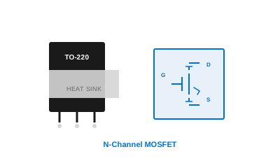
The Infineon IRFS4321PBF is a 150 V, 170 A StrongIRFET(TM) N-channel MOSFET in the surface-mount D2PAK (TO-263) package, engineered for synchronous rectification, ORing switch, and high-current DC bus switching applications where minimal conduction resistance and robust avalanche ruggedness are equally important. Its maximum RDSon of 3.4 mOhm at VGS = 10 V positions it at the top of the 150 V silicon MOSFET performance tier, enabling DC/DC converters and battery management systems to achieve rectifier stages with power densities previously requiring copper-bonded die technologies. The StrongIRFET process employs a deep trench cell architecture that concentrates the channel width per unit area, allowing the D2PAK die to handle 170 A continuous drain current with a junction temperature limit of 175 degreesC. The large molded package die-pad provides a junction-to-case thermal resistance of only 0.65 K/W, enabling heat dissipation through PCB copper planes or clip-mount heatsinks without through-hole mounting hardware. Gate charge Qg is specified at 230 nC at VGS = 10 V - a relatively high value that reflects the large die size - so gate driver current capability should be sized accordingly. The device also exhibits excellent unclamped inductive switching (UIS) ruggedness with a single-pulse avalanche energy rating of 3 J at 25 degreesC, providing margin against inductive load switching transients in high-current motor drives and DC disconnect switches. BeiLuo distributes the IRFS4321PBF in volume with documented lot traceability and provides PCB layout templates for optimal thermal performance with D2PAK copper-pour cooling.
Specifications
| Parameter | Value | Unit |
|---|---|---|
| Drain-Source Voltage VDS | 150 | V |
| Continuous Drain Current ID (25 degreesC) | 170 | A |
| RDSon Max (VGS=10V) | 3.4 | mOhm |
| Gate Charge Qg (VGS=10V) | 230 | nC |
| Gate Threshold Voltage VGSth | 2.0 - 4.0 | V |
| Single-Pulse Avalanche Energy EAS | 3000 | mJ |
| Thermal Resistance RthJC | 0.65 | K/W |
| Maximum Junction Temperature | 175 | degreesC |
| Package | D2PAK (TO-263) | |
| Body Diode Forward Voltage VSD | 1.3 | V |
Applications
- High-Current Synchronous Rectifiers
- Battery Management ORing Switches
- DC Motor Drive H-Bridges
- Server Rack Power Distribution
- Telecom -48 V Bus Converters
Documents & Downloads
- IRFS4321PBF Datasheet (0.7 MB)
- BeiLuo MOSFET Selection Guide (1.0 MB)
Frequently Asked Questions
What gate driver current is recommended to drive the IRFS4321PBF at high switching frequencies?
The IRFS4321PBF has a total gate charge Qg of 230 nC at 10 V drive. To achieve a 100 ns rise time at a 100 kHz switching frequency, a peak gate source current of approximately 2.3 A is required. Dedicated gate driver ICs rated for 2 to 4 A peak output - such as the Infineon EiceDRIVER 2EDL series - are appropriate. Reducing the switching frequency to 20 to 50 kHz allows smaller gate drivers, trading switching losses for driver simplicity in cost-sensitive designs.
Can the IRFS4321PBF be used as a synchronous rectifier in a bidirectional battery charger?
Yes. The IRFS4321PBF's 3.4 mOhm maximum RDSon and 170 A current rating make it well-suited for synchronous rectification stages in bidirectional on-board charger (OBC) designs up to approximately 11 kW at 48 V bus voltage. The body diode's forward voltage of 1.3 V is relatively high for a synchronous rectifier, so gate drive timing should enable the MOSFET channel before body-diode conduction begins in each half-cycle, minimizing dead-time losses.
How should D2PAK devices like the IRFS4321PBF be thermally managed on a PCB?
The D2PAK (TO-263) exposed die-pad should be soldered to a dedicated copper pour area of at least 1,000 mm2 on the top PCB layer. For power dissipation above 5 W, thermal vias connecting the top copper pour to an internal ground plane reduce the board-to-ambient resistance significantly. A clip-mount heatsink adhesively bonded over the molded body further reduces thermal resistance for dissipation above 10 W. BeiLuo's FAE team can provide a thermal model in PLECS or Simscape for accurate junction temperature estimation.
Is the IRFS4321PBF rated for automotive applications?
The standard IRFS4321PBF is an industrial-grade device rated for junction temperatures to 175 degreesC but not specifically AEC-Q101 qualified. For automotive applications requiring full AEC-Q101 qualification and PPAP documentation, Infineon offers the AUIRFS4321 with equivalent electrical parameters but the full automotive qualification package. BeiLuo can source both variants - please specify your qualification requirement when requesting a quote.
What is the avalanche ruggedness of the IRFS4321PBF and why does it matter?
The IRFS4321PBF is rated for a single-pulse avalanche energy EAS of 3,000 mJ at 25 degreesC starting temperature. This specification indicates the device can absorb the energy stored in a stray inductance during unclamped inductive switching without destructive failure. In practical terms, a 100 uH stray inductance with 60 A of inductor current produces an avalanche energy of 180 mJ, well within the rated limit. Avalanche ruggedness is particularly important in motor-drive H-bridges where unexpected current paths can arise during fault conditions.
Alternative Parts

Companion Parts


Ready to Order IRFS4321PBF?
Contact BeiLuo for competitive pricing, FAE support, and fast global delivery.
Download Datasheet Apply for Sample Get a Quote Ask FAE