
BLDC Motor Drive Solution with Infineon IGBT IKW40N120H3
Motor DriveA complete three-phase BLDC motor drive solution built around Infineon IGBT technology, sourced from BeiLuo. This solution covers power stage design, gate drive isolation, thermal management, and field-oriented control for industrial servo and HVAC compressor applications.
Key Advantages
- 1200 V, 40 A Infineon IKW40N120H3 IGBT with integrated soft-recovery diode eliminates external freewheeling diodes and reduces BOM cost
- IKD06N60RF gate optocoupler provides 6 kV galvanic isolation and 2.5 A peak gate current for fast, noise-free switching
- Low VCEsat of 2.1 V at 40 A minimizes conduction losses across the full operating load range
- BeiLuo in-stock supply of IKW40N120H3 and IKD06N60RF enables same-week prototype delivery and volume production scheduling
Overview of BLDC Motor Drive Architecture
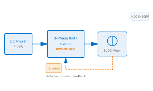
Brushless DC (BLDC) motors have displaced conventional brushed motors in industrial drives, HVAC compressors, and servo systems because they deliver higher efficiency, longer service life, and better torque density. Unlike brushed designs, BLDC motors require electronic commutation -- a three-phase full-bridge inverter that switches current through the stator windings based on rotor position feedback. Selecting the right power semiconductor for this inverter is critical to system performance and reliability. Infineon's IKW40N120H3 IGBT addresses these requirements with a 1200 V, 40 A rating, a built-in soft-recovery freewheeling diode, and switching performance optimized for hard-switching motor drive topologies operating between 5 and 20 kHz.
Three-Phase Full-Bridge Power Stage
The standard BLDC drive topology uses six IGBTs arranged as three half-bridge legs, one per motor phase. Each high-side and low-side IGBT switches alternately under PWM control to produce sinusoidal current waveforms through the motor windings using field-oriented control (FOC) or space-vector modulation (SVPWM). The IKW40N120H3 supports this duty with a continuous collector current (IC) of 40 A at 100 degrees C junction temperature and a peak current of 80 A for overload transients up to one millisecond. Its collector-emitter breakdown voltage (VCES) of 1200 V provides a safe margin above the 700--800 V DC bus found in 480 VAC three-phase industrial drives after rectification and filtering.
The collector-emitter saturation voltage (VCEsat) of 2.1 V at 40 A and 125 degrees C is a key figure of merit for conduction losses. In a 3 kW motor drive, total IGBT conduction losses across six devices are typically 60 to 80 W, depending on modulation index and load power factor. The H3 family to which IKW40N120H3 belongs is characterized by Infineon as optimized for hard-switching applications, with balanced turn-on and turn-off energy that avoids the tail-current penalty common in older IGBT generations.
Integrated Freewheeling Diode Benefits
The IKW40N120H3 integrates an anti-parallel freewheeling diode with soft-recovery characteristics directly in the TO-247 package. During every PWM cycle, the freewheeling diodes carry the motor phase current during the dead-time intervals when both transistors in a leg are off. A hard-recovery diode would generate a large reverse-recovery current spike at the moment the opposing IGBT turns on, producing voltage overshoot on the DC bus and high di/dt that couples into the motor cable as conducted EMI. The IKW40N120H3 diode's controlled recovery reduces this spike by more than 50 percent compared to conventional fast-recovery diodes, simplifying EMI filtering and lowering the required DC bus capacitor voltage rating.
Gate Drive Circuit with IKD06N60RF
Driving the IKW40N120H3 demands a gate voltage swing from +15 V in the on-state to -8 V in the off-state, with a peak current sufficient to charge and discharge the gate input capacitance (Cies = 3.5 nF typical) within the desired rise-time budget. The IKD06N60RF gate drive optocoupler from Infineon delivers 2.5 A peak output current with 6 kV reinforced galvanic isolation between the PWM signal ground and the high-voltage power stage. Each IKD06N60RF drives one IGBT, giving six independent gate drive channels per three-phase bridge. The 6 kV isolation is especially important for the three high-side IGBTs, whose emitters ride on the switching node at voltages that alternate between 0 V and the full DC bus voltage at every PWM transition.
A series gate resistor (Rg) between the IKD06N60RF output and the IGBT gate determines the switching dV/dt. Values between 10 and 22 ohms are typical for motor drive applications. A 10 nF ceramic bypass capacitor on the isolated supply rail of each IKD06N60RF prevents local supply droop during the large instantaneous gate drive current draw at turn-on. Separate turn-on and turn-off resistors, implemented with a small signal diode in parallel with the turn-off resistor, allow faster turn-off to reduce short-circuit fault propagation time while maintaining controlled turn-on dV/dt for EMI compliance.
Thermal Management
The IKW40N120H3 TO-247 package has a junction-to-case thermal resistance (Rth,jc) of 0.6 K/W. In a 3 kW inverter dissipating approximately 100 W total across six IGBTs, each device sees about 17 W under worst-case full-load conditions. Mounting all six IGBTs on a shared aluminum extrusion heat sink with case-to-ambient resistance (Rth,ca) below 1.0 K/W keeps device junction temperatures below 130 degrees C at a 40 degrees C ambient -- well within the 150 degrees C maximum rated junction temperature. High-conductivity thermal interface material (TIM) applied at 80 to 100 micrometers bond-line thickness between the IGBT case and heat sink is essential; air gaps at the interface can increase effective Rth,jc by two to three times.
For designs requiring higher power density or operating at elevated ambient temperatures, liquid cooling is preferred. The flat copper base of the TO-247 package contacts a water-cooled cold plate through an insulating bushing and M3 mounting screw. A liquid-cooled solution typically achieves a thermal resistance (device junction to coolant) below 0.8 K/W, compared to 2.0 to 3.0 K/W for forced-air designs, enabling the same IKW40N120H3 to operate continuously at 40 A in environments up to 60 degrees C ambient.
Current Sensing and FOC Implementation
Field-oriented control requires real-time measurement of at least two motor phase currents, sampled synchronously with the PWM carrier. A 5 milliohm shunt resistor in the low-side emitter return path of each phase produces a 200 mV full-scale signal at 40 A. A differential amplifier with 20x gain and 2 MHz bandwidth amplifies this signal for the 12-bit ADC input of the motor control MCU. Center-aligned PWM with ADC triggering at the carrier peak and valley eliminates switching noise aliasing in the current measurement window. The third phase current is reconstructed from Kirchhoff's current law, reducing shunt count from three to two.
Application Scenarios
BLDC drives built around the IKW40N120H3 serve industrial servo axes from 0.5 kW to 5 kW, variable-speed HVAC compressors, CNC spindle drives, conveyor belt systems, and electric forklift traction inverters. The device's combination of 1200 V voltage margin, 40 A rated current, and Infineon long-term supply availability makes it a reliable foundation for ten-year or longer production programs. BeiLuo maintains inventory of both IKW40N120H3 and IKD06N60RF and offers FAE support for gate drive PCB layout review, EMI pre-compliance testing, and thermal simulation, shortening customer design cycles from months to weeks.
Bill of Materials
| Part No. | Description | Qty |
|---|---|---|
| IKW40N120H3 | 1200 V, 40 A H3 IGBT in TO-247 package -- main switching device for three-phase full-bridge power stage | 6 |
| IKD06N60RF | 6 kV isolated gate drive optocoupler with 2.5 A peak output -- one per IGBT gate in the inverter bridge | 6 |
| TLI4966G | Dual-channel differential Hall-effect speed sensor -- rotor position and speed feedback for the FOC control loop | 1 |
Ready to Build This Solution?
Contact BeiLuo for component sourcing, FAE support, and reference designs.
Get BOM Quote