
Solar Inverter Full-Bridge Solution with Infineon IGBT and MOSFET
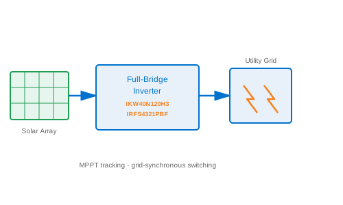
Solar PVA complete solar string inverter power stage solution using Infineon IGBT and OptiMOS MOSFET devices sourced from BeiLuo. This solution covers MPPT boost converter design, H-bridge IGBT inverter topology, grid-tie synchronization, anti-islanding protection, and thermal management for residential and commercial rooftop PV systems from 3 kW to 30 kW.
Key Advantages
- Infineon IKW40N120H3 IGBT handles 1200 V blocking voltage with 40 A rated current, providing a 50 percent voltage margin above the 800 V DC bus in grid-tied string inverters
- Infineon IRFS4321PBF MOSFET in the MPPT boost stage achieves 3.5 milliohm RDS(on) for low conduction losses across the full 100 to 800 V PV string voltage input range
- Combination of Infineon IGBT and MOSFET topology achieves European Weighted Efficiency (ETA-Euro) above 97 percent at 30 kW string inverter power level
- BeiLuo in-stock supply of IKW40N120H3 and IRFS4321PBF supports both engineering evaluation and volume inverter production with verified Infineon authenticity
Overview of Solar String Inverter Power Stage
Grid-tied solar string inverters convert variable DC power from photovoltaic (PV) strings into AC power synchronized with the utility grid. Achieving high conversion efficiency across the wide PV string voltage range (100 to 550 V open-circuit depending on temperature and irradiance) and the variable load profile of a grid connection requires a two-stage power architecture: a maximum power point tracking (MPPT) boost converter that steps up the PV string voltage to a stable 800 V DC bus, followed by a full-bridge IGBT inverter that synthesizes a 50 Hz or 60 Hz sinusoidal output. Infineon's IKW40N120H3 IGBT and IRFS4321PBF OptiMOS MOSFET are the cornerstone power semiconductors for these two stages. BeiLuo stocks both parts and supports inverter manufacturers from design review through mass production supply.
MPPT Boost Converter with IRFS4321PBF
The MPPT boost converter elevates the PV string voltage from as low as 100 V (at low-irradiance winter mornings) to the regulated 800 V DC bus required by the inverter stage. The IRFS4321PBF N-channel OptiMOS MOSFET handles the boost converter switching duty with a 150 V VDSS rating -- more than adequate for the 100 to 550 V PV string input, where the MOSFET switch sees a voltage equal to the output bus voltage minus the PV string voltage during off-time. The IRFS4321PBF's RDS(on) of 3.5 milliohm at 25 degrees C (approximately 5.5 milliohm at 100 degrees C) yields conduction losses of less than 8 W at a 30 A peak boost inductor current in a 10 kW string inverter, contributing to European Weighted Efficiency above 97 percent.
The MPPT algorithm implemented in the inverter DSP continuously perturbs the boost converter duty cycle and observes the change in PV power output to track the maximum power point on the PV I-V characteristic curve. The Perturb and Observe (P and O) algorithm with 50 millisecond step period converges to within 1 percent of true MPP under stable irradiance conditions. The IRFS4321PBF's fast switching speed (rise time below 20 nanoseconds at 100 kHz gate drive) allows the boost converter to operate at 100 kHz, minimizing boost inductor size and weight -- an important consideration for string inverter housing designs.
H-Bridge IGBT Full-Bridge Inverter
The single-phase H-bridge full-bridge inverter for residential systems uses four IKW40N120H3 IGBTs arranged as two half-bridge legs. The switching frequency for grid-tied inverters is typically 16 kHz for single-phase designs and 8 to 10 kHz for three-phase designs, chosen as a compromise between output filter size and switching loss. At 16 kHz, the IKW40N120H3 Eon + Eoff switching energy (typically 2.5 mJ at 40 A and 600 V) results in approximately 40 W switching loss per IGBT pair, adding to the conduction loss for a total inverter bridge loss of 80 to 100 W in a 5 kW system.
The H-bridge modulation strategy uses unipolar sinusoidal PWM (USPWM), in which the two bridge legs switch in opposition with a phase shift, producing a three-level voltage waveform at the output filter terminals. Compared to bipolar SPWM, USPWM halves the effective switching frequency seen by the output LCL filter, allowing the filter inductor and capacitor values to be halved without degrading total harmonic distortion (THD) below the 5 percent IEC 61000-3-2 limit. The IKW40N120H3's soft-recovery integrated freewheeling diode is essential in unipolar PWM, where the freewheeling diode must recover at twice the PWM carrier frequency.
Three-Phase Inverter Configuration
For commercial rooftop PV systems from 10 to 30 kW, a three-phase full-bridge inverter uses six IKW40N120H3 IGBTs. The three-phase bridge delivers 400 VAC three-phase (line-to-line) output at 50 Hz with THD below 3 percent using a space-vector modulated (SVM) carrier at 8 kHz. Six isolated gate drive channels from six IKD06N60RF optocouplers drive the IGBT gates independently, with hardware interlocks preventing simultaneous conduction of both IGBTs in a phase leg. The 1200 V VCES rating of IKW40N120H3 provides a 50 percent voltage safety margin above the 800 V DC bus, accommodating transient overshoot of 20 to 30 percent during hard switching without requiring additional snubber circuits.
Grid Synchronization and Protection
The inverter firmware implements a phase-locked loop (PLL) algorithm that synchronizes output current with the grid voltage fundamental frequency. The grid voltage zero-crossing is detected by the ADC at 20 kHz sampling rate, and the PLL bandwidth is set to 10 Hz to reject harmonics and frequency noise while tracking slow grid frequency deviations within the plus or minus 0.5 Hz range specified by EN 50160. Anti-islanding detection uses the Sandia Frequency Shift (SFS) algorithm, which injects a small frequency perturbation into the inverter output; if the grid is disconnected, the inverter frequency drifts beyond the detection threshold within 0.5 seconds and the inverter shuts down, satisfying IEEE 1547-2018 anti-islanding requirements.
Thermal Management
Solar inverters operate continuously at full power during peak irradiance hours and must manage the accumulated junction temperature of the IGBT and MOSFET devices over a 20-year service life. IKW40N120H3 has a power cycling endurance specification of more than 1,000,000 cycles at 25 degrees K junction temperature swing, which corresponds to more than 20 years of daily sunrise-to-sunset power cycles in a 30 kW string inverter. The TO-247 package copper base plate mounts to an extruded aluminum heat sink inside the inverter housing. Combined forced-air cooling with a 60 mm DC fan and a heat sink thermal resistance of 0.3 K/W per IGBT keeps the junction at below 120 degrees C even on 40 degrees C ambient summer days.
Application Scenarios and BeiLuo Supply
Infineon IKW40N120H3 and IRFS4321PBF power the MPPT and inverter stages in residential string inverters from 3 to 10 kW, commercial three-phase inverters from 10 to 30 kW, and utility-scale paralleled string inverter arrays above 30 kW. BeiLuo maintains volume stock of both components with CE-compliant lot traceability and Infineon authenticity guarantees. Our FAE team provides gate drive PCB layout review, LCL filter design calculations, anti-islanding algorithm parameter tuning, and compliance documentation support to help inverter manufacturers achieve IEC 62109 and grid-connection certification efficiently.
Bill of Materials
| Part No. | Description | Qty |
|---|---|---|
| IKW40N120H3 | 1200 V, 40 A H3 IGBT in TO-247 -- H-bridge inverter switching device in the grid-tied full-bridge stage | 4 |
| IRFS4321PBF | 150 V N-channel OptiMOS MOSFET in D2PAK -- MPPT boost converter switch handling 100 to 550 V PV string input | 2 |
| XMC4700-F100K2048 | 144 MHz ARM Cortex-M4F MCU with CCU8 PWM unit -- MPPT algorithm and grid-synchronization control loop | 1 |
Ready to Build This Solution?
Contact BeiLuo for component sourcing, FAE support, and reference designs.
Get BOM Quote